A small zero offset can alter an accumulated charge estimate long after the individual readings appear plausible. The error matters because battery management uses current over time, including intervals when little current flows.
The fluxgate design in the Hangzhi BMS range supplies isolated measurements over CAN, connecting the current sensor to the controller’s calculations. Accurate sensing supplies the input to that chain; the battery-management controller interprets the data and carries out charging, discharging and protection functions.
Follow Current into the Charge Calculation
Charge transfer is obtained by integrating current over an interval. Integrating amperes against seconds gives coulombs, while integration against hours gives ampere-hours. A constant measurement offset contributes to the accumulated result throughout the interval, so an error near zero can remain consequential even when the system spends much of its time carrying modest current.
The current sensor provides a measured signal for that calculation and for monitoring charging or discharging. State-of-charge estimation also needs the controller’s interpretation of the accumulated charge; the measuring element does not perform the complete management task.
In a vehicle, a sensor in a BDU or SBOX circuit can measure total battery current, supplying information used for charge control and overcurrent or overcharge protection.
An integration-based state estimate also requires a starting point and an appropriately defined usable capacity. Current integration tracks a change from that starting point, so correcting the current baseline cannot remove an initial estimation error. The controller remains responsible for combining its inputs and maintaining the state estimate.
Cover Large Currents Without Losing the Low-Current Context
Fast charging and low-current operation place different demands on the same battery current sensor. A broad input range accommodates substantial current, while zero-point behavior matters when the useful signal is small. Evaluating both conditions connects the nominal rating to the current history that the controller will accumulate.
The BMS300 has a nominal DC range of ±300 A. Its nominal room-temperature error is 0.1%, while its temperature-range error is 0.5% with a ±3σ condition. Those entries preserve the distinction between the room-temperature assessment and performance across temperature; neither supplies a numerical prediction of accumulated state-of-charge error for an unspecified operating history. A percentage specification also needs its reference quantity before conversion into amperes.
Higher-current configurations have their own ratings. BMS500 is rated at ±500 A nominal DC with a ±530 A primary overload figure; BMS1500 has corresponding figures of ±1500 A and ±1550 A. The overload entries remain attached to their individual configurations and do not establish unrestricted operation above the nominal range.
Deliver the Measurement with the Correct Timing and Format
At the receiving interface, the current sensor becomes a participant in a defined communication exchange. The BMS300 from Hangzhi uses CAN 2.0B at 500 kbit/s, with big-endian byte order and an eight-byte current-return frame. Its cyclic transmission interval is 10 ms with a ±1 ms tolerance, specifying the period at which those frames are sent rather than an absolute time window.
Correct byte interpretation preserves the intended numerical meaning of the transmitted data. The current value occupies a defined field within the eight-byte frame, with a fixed scale factor converting the raw count to amperes; both the field position and the scale factor must be taken from the device data sheet before the frame can be decoded. The controller also needs to associate measurements with elapsed time when accumulating charge, since a sequence of current values without an appropriate interval cannot define the transferred quantity.
The CAN bit rate describes communication speed and does not independently establish the sensing element’s response time. Where current varies between updates, the integration method must approximate the intervening history; the reported values alone do not reconstruct every unobserved change within that interval.
An external 120 Ω termination resistor is required for the BMS300. Message format, transmission cycle and the required electrical termination therefore enter the interface design together, connecting the measured quantity to the controller that receives it.
Preserve the Electrical Conditions Around the Device
A battery current sensor installed near the high-voltage bus still needs its own suitable low-voltage supply and operating environment. Full accuracy for the BMS300 requires an 8–16 V supply, and its stated ambient operating range is −40°C to +85°C. Supply and temperature are part of the conditions under which the onboard measurement is assessed.
Electrical isolation separates the measurement electronics from the high-voltage current path. For the BMS300, the insulation test is 2.5 kV RMS at 50 Hz for one minute. Specified creepage is 7.2 mm and clearance is 6.95 mm, adding distinct physical spacing values to the electrical insulation assessment.
The insulation test identifies a voltage, waveform frequency and duration; it cannot by itself specify the continuous working voltage permitted throughout an installed battery system.
Use Production Tests to Examine the Sampling Task
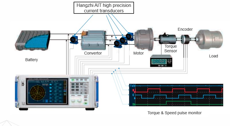
Battery-production monitoring and end-of-line equipment also require current sampling and feedback. The AIT fluxgate devices and the BMS series share the same fluxgate measurement platform but serve different ends of the chain: AIT devices feed test-equipment functions, where the sampling element contributes to the bench’s measurement loop, while the BMS series provides the onboard CAN output described above. Their use concerns the equipment assessing the battery, alongside the onboard chain that later supplies measurements to battery management.
Connections, temperature, long-term drift and thermal electromotive forces can affect traditional shunt-based test arrangements. Examining those influences addresses the integrity of the bench measurement. The AIT test-feedback role and the CAN-output BMS role consequently retain their own receiving equipment and connection requirements.
Once current data reaches the controller, the accumulated result depends on both the measured values and their treatment over time. The Hangzhi BMS arrangement supplies measurements within specified electrical, environmental and communication conditions, while management calculations and protection remain controller responsibilities.
Practical Checklist for Integrating the Current Measurement
- Record the reference quantity behind each percentage: 0.1% at room temperature and 0.5% over temperature are both relative to nominal current, and the ±3σ condition defines a statistical coverage limit rather than a worst case.
- Convert the percentage figures to amperes at the actual nominal rating before estimating their effect on accumulated charge.
- Keep the 10 ms ±1 ms transmission period, the CAN bit rate and the sensing element’s response time as separate quantities; none of them substitutes for another.
- Confirm the current field position and scale factor from the data sheet before decoding the eight-byte frame.
- Provide the external 120 Ω termination and verify the 8–16 V supply and −40 °C to +85 °C ambient range before expecting the stated accuracy.
- Treat the 2.5 kV RMS insulation test as a test condition, and derive the continuous working voltage from creepage, clearance and the installation’s pollution degree, material group and overvoltage category.
- After an overload event, confirm that the configuration’s overload rating has not been exceeded and that the output still tracks primary current before resuming integration.
